

Check out some of the recent mobile devices, like last year’s iPhone 5S or Galaxy S4, and you will see several new features in them. Any person who has not kept up with technology over the past decade will find these to be magical, and with good reason. Almost all modern ‘smart’ electronic devices around us have accelerometers or gyroscopes, or even both together. Together these enable functionality in devices that make them seem magical to a lay user.
If you are a regular reader of this section, you should be now somewhat familiar with sensors and their functions. However, just to provide a small insight, a sensor is a component or a device that either detects or measures any physical property and indicates, records or responds to it. There are a number of sensors in the market today; however, motion sensors are the ones that are most widely used in applications for their better performance. they detect and measure different types of motions of a device that may further be used as an input to the control system for that particular device. We all are aware of the different types of motions like vibration, rotation, acceleration, etc. All these motion types have a special type of sensor for their detection, like accelerometers are used for the detection of acceleration with a free-fall reference, and gyroscopes are used to detect the orientation of the device directly.
Together, an accelerometer and a gyroscope can provide enough data to detect motion on six axes—up and down, left and right, forward and backward, and roll, pitch and yaw rotations.
Tekedia Mini-MBA edition 14 (June 3 – Sept 2, 2024) begins registrations; get massive discounts with early registration here.
Tekedia AI in Business Masterclass opens registrations here.
Join Tekedia Capital Syndicate and invest in Africa’s finest startups here.
What are they?
An accelerometer is a type of sensor that senses the velocity and the motion of a reference mass to track its orientation and movement. It is an electromechanical device that can help a gadget understand its surroundings in a better way.
On the other hand, a gyroscope is a type of sensor that is used to measure and maintain the orientation of a device or of a reference object using the principle of angular velocity. It is another type of motion sensor. It is usually referred to as a ‘gyro’ or an ‘angular velocity sensor’ or an ‘angular rate sensor.’ The angular velocity sensed by the sensor is converted into an electrical signal.
Says T. Anand, promoter and managing director of Knewron, “There are a couple of applications where we have deployed accelerometers. One such application is a security device that is mounted and should remain stationary under normal conditions. However, in case someone tries to tamper with it, even slightest movement or vibration would be sensed and the device would come into action. Another application is for special-purpose objects that would be deployed in events, and these objects would sense movement or activity done by the user. Depending upon the activity, user updates would be registered on his social profiles.”

Parameters to select an accelerometer and a gyroscope
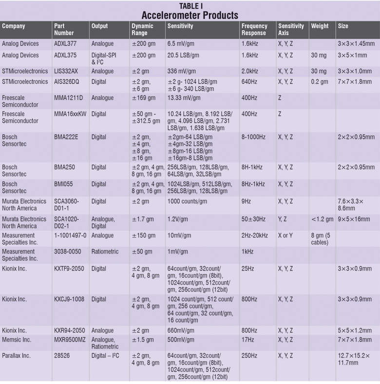
Each component or a device has some parameters based on which it is selected. Now identification of those parameters becomes difficult when there are ‘n’ number of similar products in the market, highlighting different parameters. Following is the list that would help us identify the correct parameters to select an accelerometer:
1. Analogue/digital output. An accelerometer with an analogue output provides a continuous voltage that is proportional to the acceleration, whereas in an accelerometer with digital output, the amount of time is high and will be proportional to the amount of acceleration.
2. Dynamic range. It is the maximum amplitude measured by an accelerometer before it distorts or clips the output signal. It is specified in g’s.

3. Sensitivity. It is the scale factor of a sensor that is measured in terms of change in output signal for every change in the input measured. It is measured in mV/gm.
4. Frequency response. It measures the limit of the frequency for the sensor-detected motion and the reported output. It is measured in hertz (Hz).
5. Sensitivity axis. The inputs detected by the accelerometers are always in reference to an axis. Single-axis accelerometers can detect inputs only along one plane whereas tri-axis accelerometers can detect inputs from any direction. So the tri-axis accelerometers are used in most of the applications.
6. Size and mass. Both the size and the mass of an accelerometer should be small as compared to that of the system to be monitored, otherwise it can affect and also change the characteristics of the object that is being tested.
The micro-electro-mechanical sensor (MEMS) accelerometer is special as compared to other accelerometers owing to its capability and small size. “The parameters to select an MEMS accelerometer are power consumption, sensitivity to ‘g’ force, ADC bit size, device calibration, axis support and presence of internal FIFO data buffer. Newer accelerometers support additional features such as free-fall detection, motion detection, gesture control and orientation detection algorithms, so designers can exploit these features depending on the application requirements,” says Avinash Babu, senior project manager, Embedded Systems, Mistral Solutions.
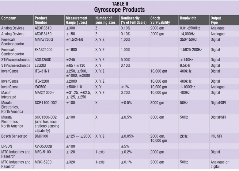
So some points on the basis of which a gyroscope can be selected are:
Measurement range. It specifies the maximum angular speed measured by the gyro sensor. It is measured in degrees per second (°/sec).
Number of sensing axes. A gyroscope can measure angular rotation either in one, two or three axes; however, a multi-axis gyro has multiple single-axis gyros that are oriented orthogonally to one another.
Non-linearity. It specifies the closeness of the output voltage to linearity and is proportional to the actual angular rate. It is measured either as an error in percentage or in parts per million (ppm).
Shock survivability. Since both the linear and angular rotations occur in a gyroscope, it is necessary to check the force it can withstand without falling. However, a gyroscope is expected to withstand very large shocks (measured in g’s) without breaking.
Bandwidth. It is the number of measurements made in one second. It is quoted in hertz (Hz).
Angular random walk (ARW). It is the measurement of gyro noise in deg/hour1/2 or deg/sec1/2.
Bias instability. It measures the goodness of a gyro in degrees per hour (°/hr).
Challenges faced by the design engineers
Technology brings challenges and the designers have to overcome all these in order to create something new. Babu says, “Placement of a sensor on the PCB is very crucial and is often overlooked. For optimal motion detection, a sensor needs to be placed away from the centre of the device, which helps to ensure better acceleration readings and makes them more significant in the detection of smaller motions from a higher moment of inertia than when they are placed right on the centre of the movement.
“Care must be taken to ensure that the package is not stressed by holes, or components on the PCB are not placed too close to the accelerometer. It is important to place the sensor where it is not vulnerable to be pushed or otherwise affected directly by the user’s hands. It is good to avoid placing the sensor near components that may have large temperature variations, or that are constantly very hot, as this will affect the offset of the sensor.”
“Footprint of the sensor, supply current and cost need to be minimal in all consumer applications. Functional safety and reliability of the sensor in vast operating conditions becomes a major challenge in automotive applications,” explains Vikas Choudhary, engineering manager, MEMS and Sensors at Analog Devices, Inc. The other challenges are power consumption, sensor integration and calibration.
“In battery-operated devices, the power consumed by the sensors should be minimised as much as possible and the sensors must support low-power mode in suspend, preferably with interrupt functions. This would help the host processor to get relieved from the continuously polling data. Even though enough care is taken during the layout phase, there are uninterrupted interferences to these sensors due to which they report inaccurate values. Thus there is a need for the calibration of these sensors and the use of a fine-tuned software for an optimum calibration,” explains Babu.
This is not all. The other factor that can affect the working of these sensors to a larger extent is the electromagnetic interference, especially the very high frequency (VHF) EMF. T. Anand says, “Electromagnetic interference can produce false signal outputs. On the other hand, VHF-level electromagnetic interference can also cause intermodulation distortion and produce low-frequency measurement errors.”
What is new in this segment?
Sony Ericsson’s shake control and Samsung’s motion play are examples of new technologies that make good use of an accelerometer. Microsoft uses accelerometer-based features in its Windows Embedded Compact for different touch-screen applications on Windows 8. Manufacturers also use them in devices to protect their hard drives from getting damaged in case of a free-fall.
Industries currently use MEMS-based accelerometers. They work on the principle of displacement of a small proof mass that is etched into the silicon surface of the IC and is suspended by small beams. As soon as the acceleration is applied to the device, a force is developed that displaces the mass. The support beams that act as a spring, and the fluid trapped in the IC that acts as a damper, result in the second-order lumped physical system which acts as the source of non-uniform frequency response and limited operation bandwidth of the accelerometer.
On the other hand, new gyroscopes have been launched by companies like Epson for car navigation applications. KMX61G is the world’s first micro-smp magnetic gyro launched in 2013 by Kionix, with an integrated sensor fusion technology. This reduces the current drawn by up to 90 per cent as compared to the other traditional gyros. New components like these would allow product designers to incorporate the gyro functionality in products that were restricted in the past from the inclusion of gyro due to their high-power consumption.
Enhancing flexibility
When swapping similar components, engineers always know that not all components are created equal and they will always be mismatched. However, mistakes will always happen and sometimes they tend to be the expensive ones.
Let us consider what happened to Apple’s iPhone 5S—by switching the accelerometer from a STMicroelectronics LIS331DLH to a Bosch Sensortec BMA220, the phone literally lost its sense of balance. Now companies like Kionix are coming out with performance optimisation tools that allow a designer to manipulate power and noise levels through a downloadable GUI. This helps them tune the sensor to meet their system’s potentially unique requirements through precise design parameter choices.
Rugged seems to be the keyword
It comes as no surprise though, that the sensor which is used to detect a free-fall should not be the first one to bonk out on impact.
The bias stability for gyros may be pretty numbers in the datasheet, but everything goes out of the window once you get your device out into the real world. Gravity sensitivity and environmental factors like heat, all play a part here. This is why bias stability and vibration rejections are some of the key parameters being looked at. Analog Devices’ ADXRS64x family of low-noise, vibration-rejecting yaw rate gyroscopes are drop-in performance upgrades to existing designs using the ADXRS62x family.
For modern applications such as oil-downhole monitoring, UAV inertial measurements and industrial robotics, there is an increased demand for rugged accelerometers. Of course, another area that requires these accelerometers is the exponentially growing mobile devices segment. With this demand in mind, the last year has seen the launch of tougher accelerometers that can withstand heavy impacts.
A new line of sensors that are insensitive to temperature changes or gradients, with signal output unaffected by electromagnetic interference, and requiring no warm-up time was brought out by Silicon Designs in the last half of 2013. All Silicon Designs’ accelerometers feature a custom-integrated circuit with onboard sending amplifier and differential output stage, with a 0.5V-4.5V single-ended or ±4V differential output, proportional to the amount of measured acceleration.
Laser accelerometers
Researchers at Caltech, the California University of Technology, are working on accelerometers that work with lasers. An accelerometer normally uses an electrical circuit, whilst a laser accelerometer uses laser light instead of electricity. The optical cavity of this accelerometer is very small (about 20 microns long, only a single micron deep and few tenths of a micron thick). It contains two silicon nanobeams that are situated in an accelerometer as the two sides of a zipper that has a proof mass attached to one of its sides.
The moment a laser light enters the accelerometer, the nanobeams act as a ‘light pipe.’ These nanobeams guide the light to be bounced back and forth in between its holes. The movement of the proof mass results in the change of the intensity of the laser light that is reflected out. This reflected laser light is so sensitive to the motion of the proof mass that it helps in the determination of even the slightest displacement.
The laser accelerometers are still under research to find the cost-effective ways of using laser with accelerometers.
Sneha A, Gurgaon and Dilin Anand all of EFY